Imaging System Simulation
GitHub: https://github.com/Amarthgul/ISS
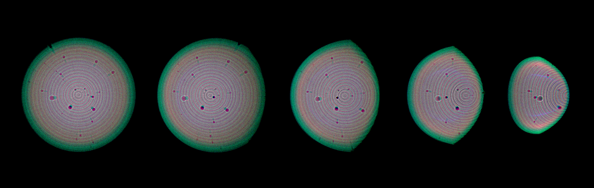
The geometric part of the tracing system also makes transformations very quick to perform, and modulations to the direction or position can be modeled in very high efficiency. The image on the right shows de-focused bokeh with onion ring patterns caused by the manufacturing process of aspheric surfaces, and many dust specks are sparkled along the lens to create the local textures.
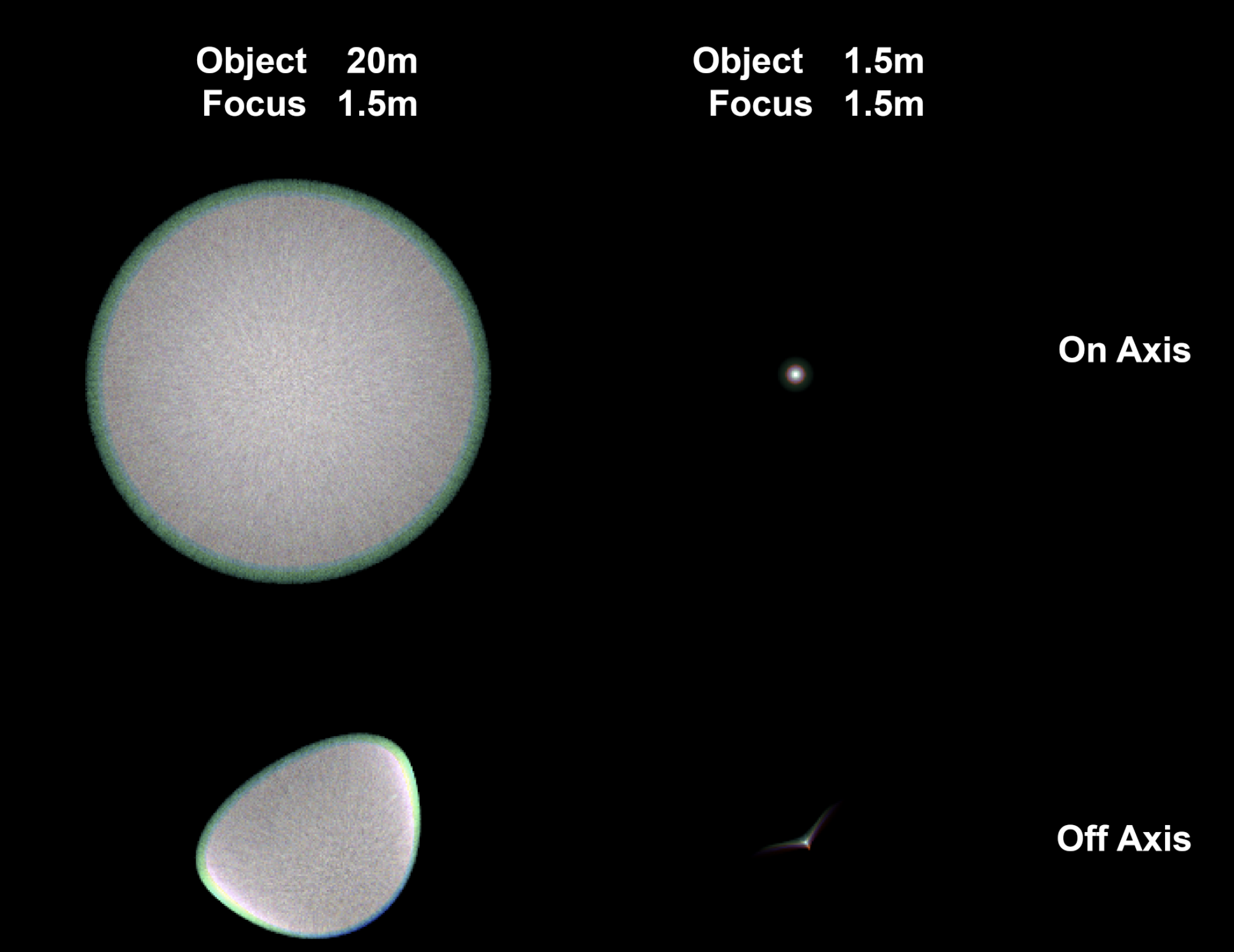
Having the imager as a separate class also allows easy control over the image resolution, combined with CUDA, the framework allows fast tracing over a high sample count. The neighboring images shows spot tracing on a 24MP imager. Note that due to the conservation of energy, the off-focus spots were overexposed for about 6 stops to have a comparable brightness.
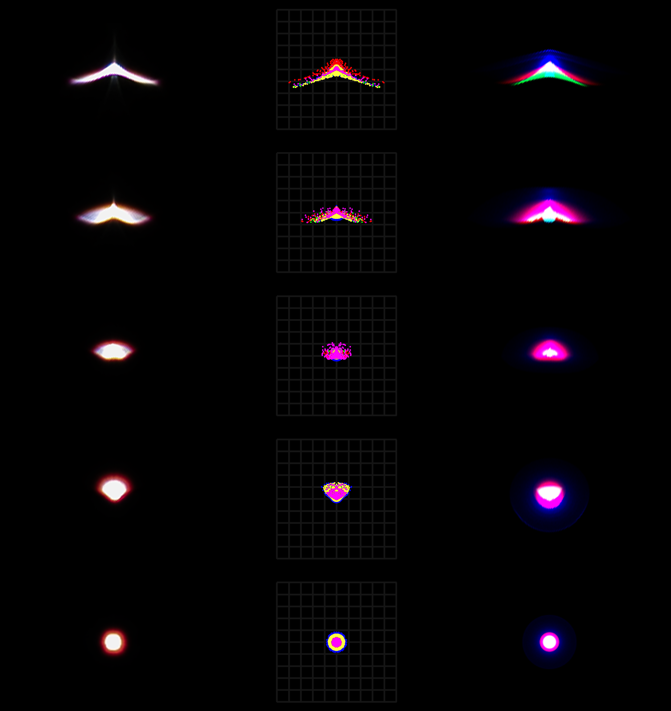
The image on the left shows a spot comparison between real photo results (leftmost), Zemax spot wavelength distribution (middle), and image simulation from this framework. The lens is the same EFL 50 1.2, real photos shot on a Canon R6II.
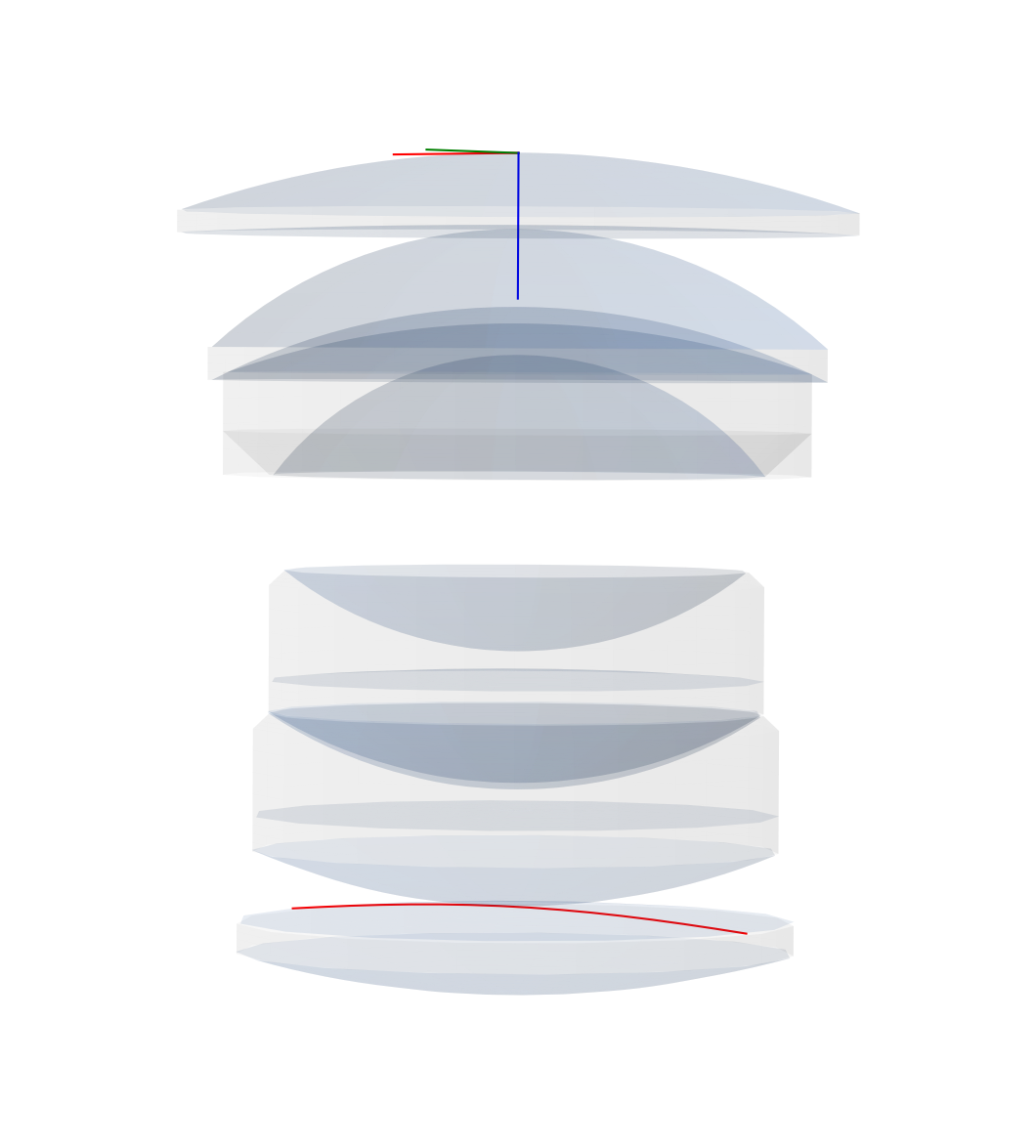
Similar to Zemax OpticStudio, the framework models the lens by defining different surfaces. It can also directly read from a ZMX file and construct the lens. In addition to the explicitly defined surfaces, the framework also uses the clear semi-diameter of each surface and constructs the boundary surfaces that encloses the surfaces into lenses (singlets, doublets, etc.).
The image on the left shows the surfaces constructed from the Canon EF 50mm f/1.2 L patent (JP 2007333790 Example 1). The red contour on the last element is the sag line of aspheric surfaces for easier observation.
Different from Zemax or CodeV, the framework also contains a class for imager, thus allowing results to be presented in the form of RGB images rather than wavelength distributions or frequency modulation (while the process is still being done entirely in wavelength and radiance, with consideration of polarization). This helps better visualize the result in a more intuitive way.
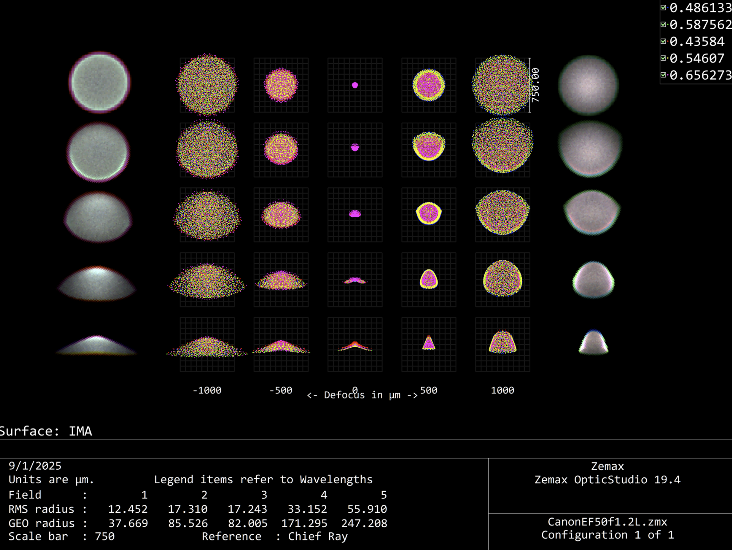
The image on the left shows a Zemax through focus spot diagram, with the simulated RGB results from this framework superimposed at the two sides.
Sequential imaging
(if you are a production person, cinematographer or animator, feel free to skip this part and just go to Aperture Control section for rendering examples)
The framework performs fast sequential imaging of the things in object space.
The GIF on the right shows an ISO12233 chart shot through a Biotar 50mm f/1.4 lens. The chart is placed at different distance and scaled to fit the field of view, showing the distortion and focus breathing of the lens.
Manipulating the virtual lens is the same as using a real one, aperture can be set to a certain f-number like a real lens. User can either manually adjust the focus distance, or type in a distance and the system will auto-focus to that distance.
While not technically a form of non-sequential imaging, the framework does work with pure reflective surfaces and supports the calculation of mirror or catadioptric lenses.
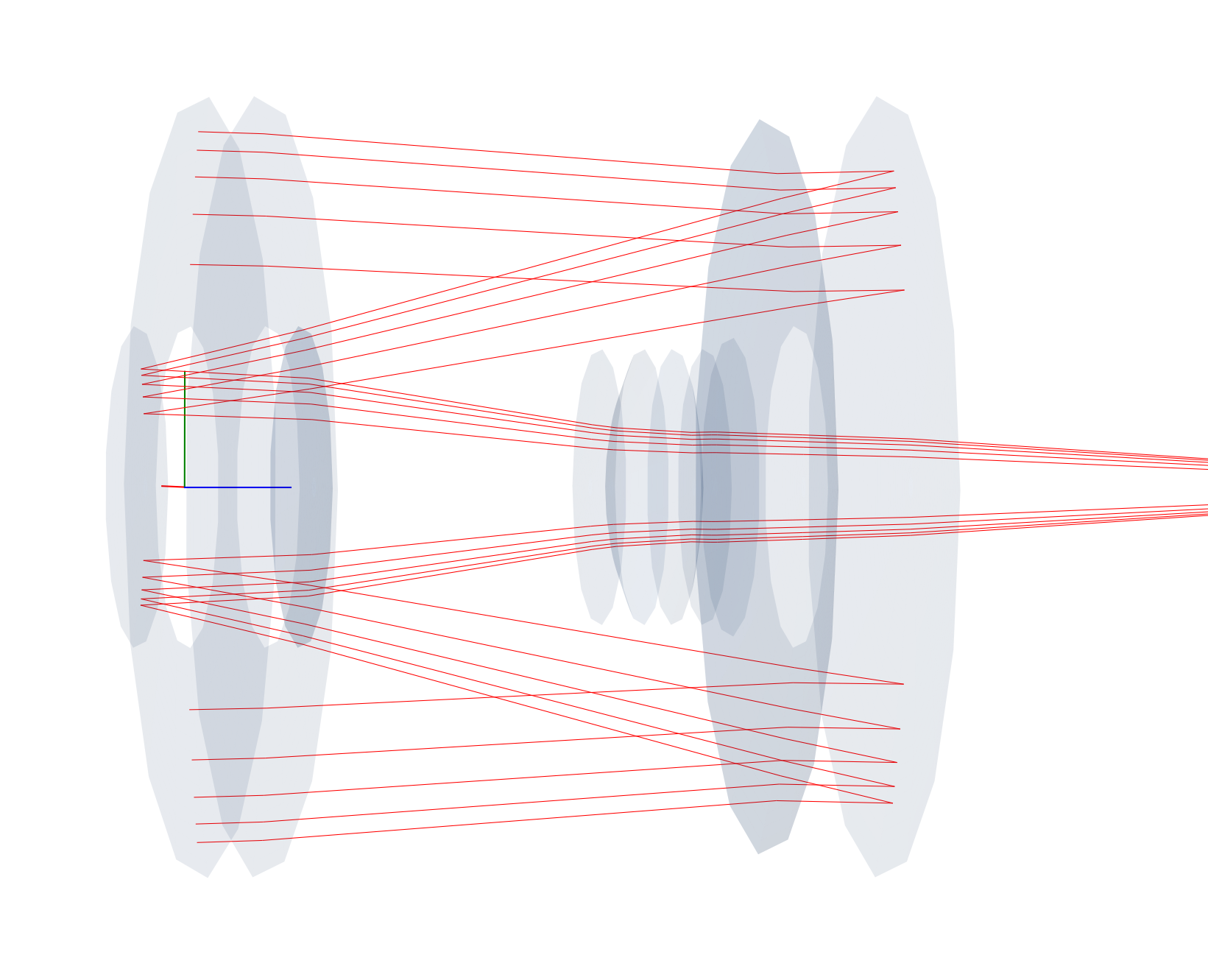
The image on the right shows the on-axis collimated rays propagating through a Tamron AdaptAll 55B 500mm f/8 lens. As always, the lens data can be directly loaded from Zemax files instead of being manually entered.
Non-sequential imaging
At the same time of performing sequential imaging, the framework also keep a a track of non-sequential rays.
If needed, the non-sequential rays can be extracted and traced over to yield the result of flare and glares. The effect takes into consideration not only primary optical surfaces, but also lens edges, blackening, and the metal inner lens barrel.
The user can also apply anti-reflection coatings to specific surfaces, making flare and glare effects art-directable.
Continuous Wavelength
One common pitfall for many similar applications trying to recreate optical effects such as chromatic aberration is that they simply scales and offsets the RGB channel, or at best assigning each color a wavelength and use that fixed wavelength to perform tracing (Looking at you, Mantra). Such approach works on thumbnail-sized image but falls apart when encountering a high-dispersion material or large de-focus.
This framework uses three sets of customizable probability density function (PDF) to model the wavelength of an RGB source, with thousands or millions of Monte Carlo iterations, effectively converting the wavelength distribution into a continuous spectrum rather than some pre-selected Fraunhofer lines. Additionally, an indexed RGB PDF-wavelength approached entirely removes the burden on the detector side to perform weighted wavelength to RGB conversion, it also allows both the emission and detector to have different PDF as either emitter spectral distribution or receiver spectral response.
Aperture control

Historically, in most photographic applications, the lens is not used wide open, i.e., at its biggest aperture opening. However, many similar applications do not consider this situation and defaults to only simulate the lens wide open. This leaves many effects unobtainable, with the most obvious one being the shape of the out-of-focus spots.
The framework, however, not only could simulate stopping down apertures, but it also supports simulating the shape created by aperture blades. The user could define different aperture blades and constructing a diaphragm from them, the framework can then accurately recreate any type of aperture and, consequently, any bokeh shape.
When given a aperture value, the framework compares the size of the theoretical entrance pupil size between the maximum aperture and the desired aperture, calculating an area ratio. Induvial blades are then rotated, the framework keeps updating the resulting area ratio and automatically adjust the degree of rotation to make sure it stops at the the exact aperture value. Additionally, the diaphragm is linked directly to the pupil. As such, when set to sample from pupil rather than 1st surface, no samples will be wasted due to reduced aperture size.
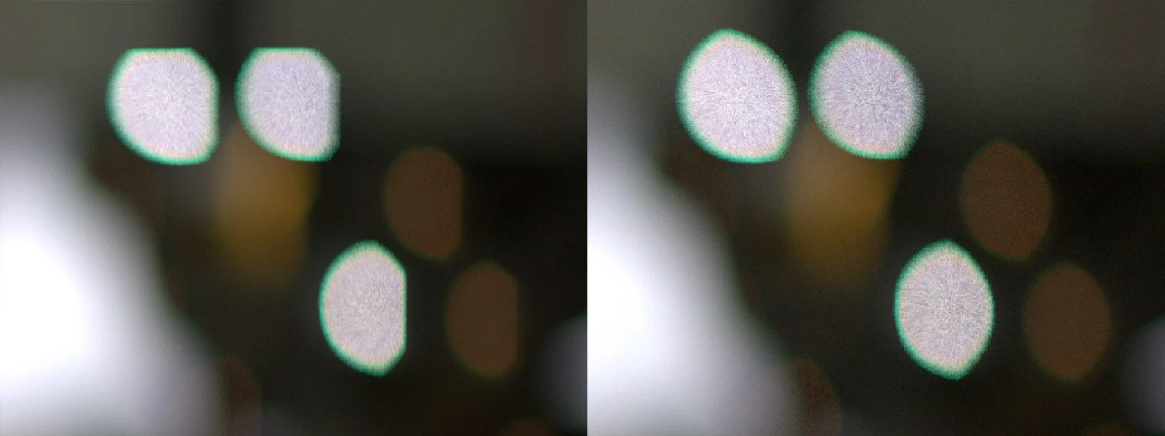
Anther important visual influence caused by the aperture is that it could impact off-axis aberrations significantly. The two-spot animation on the left shows the central and off-axis de-focus spot, notice how as the aperture stops down, the off-axis spot first looses its hard edge before changing the shape.
In the example scene above, the bokeh shape reflects the change of aperture. Additionally, as the aperture stops down, the vignette reduces and depth of field increases - both are not coded and is the natural result emerging from the physical process of a smaller aperture stop.
While in most photographic applications, “aperture” is the diaphragm that opens and closes, the thing that was just shown above. Optically, “aperture” refers to any components that restricts light, which would also include elements that are often entirely ignored: the external cine rigs.
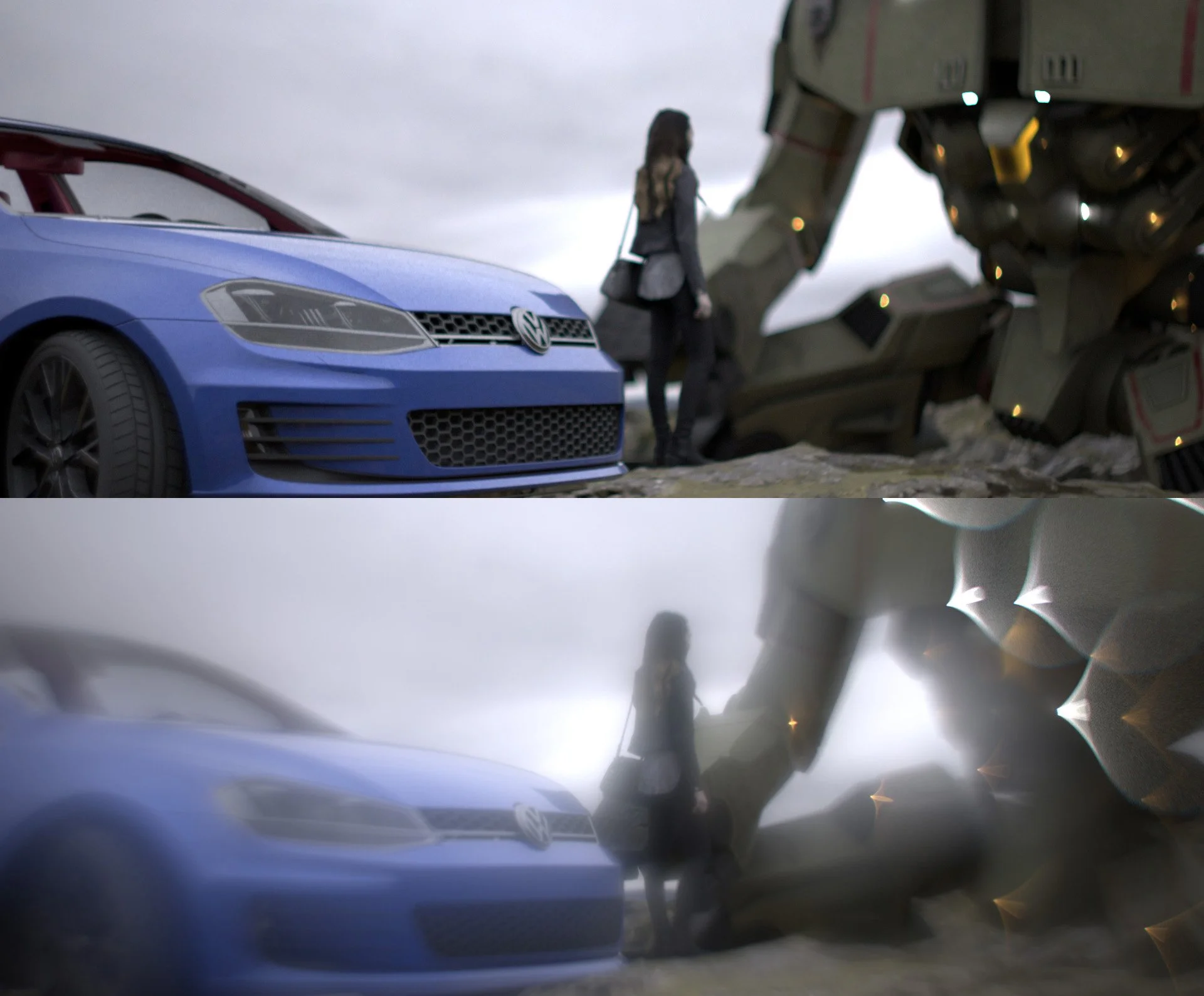
For example, on virtually all production sets, the lens has three contact points: the camera body, the rail support, and a matte box. the matte box is designed to reduce stray lights from entering the lens, thus causing flare; it also serves as the housing for circular and rectangular filters. However, while the matte box can reduce unwanted lights, it also partially obscures ordinary lights sources within the frame, which will result in bokeh around the edge to be cut.
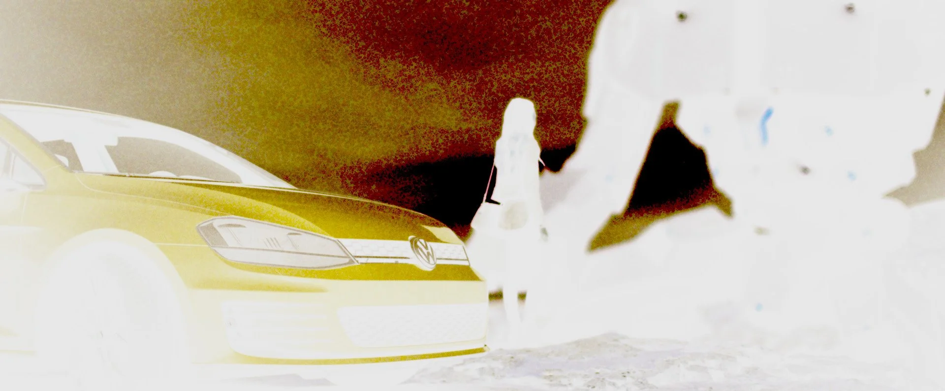
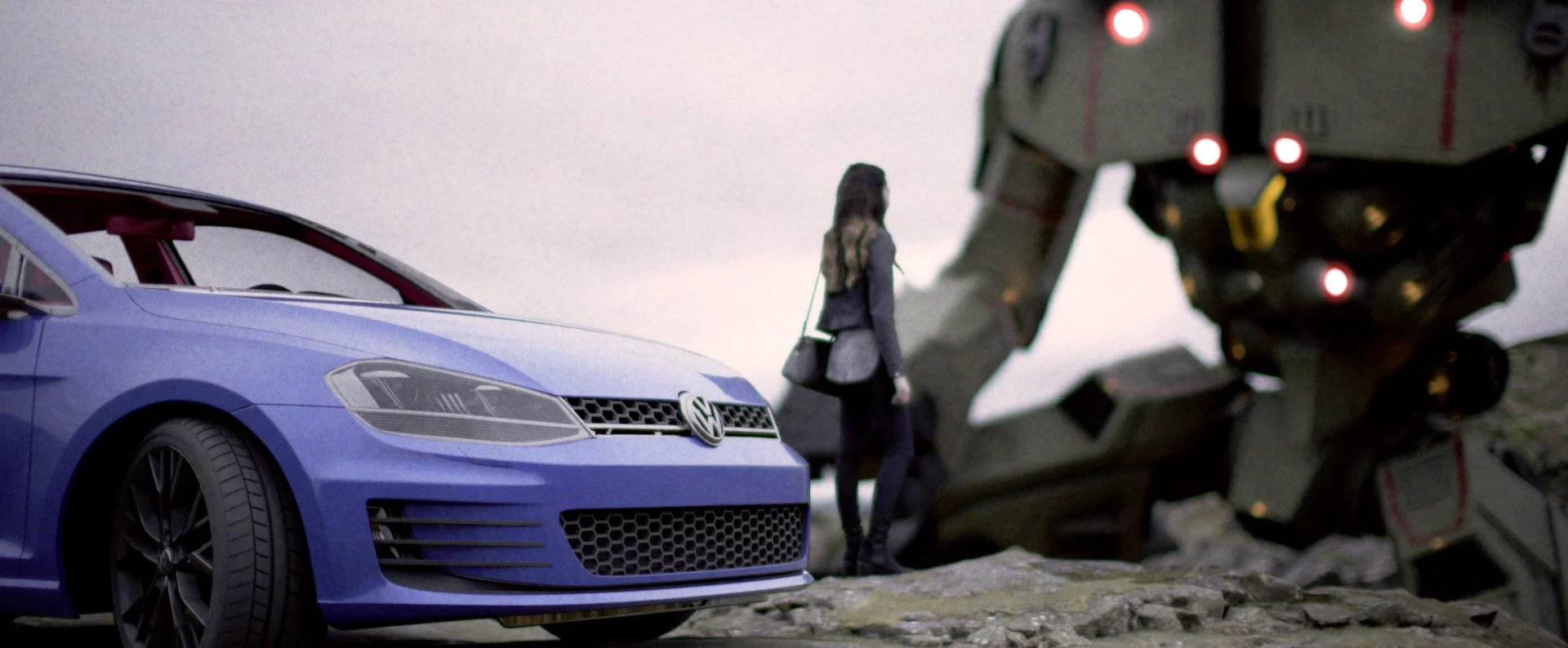
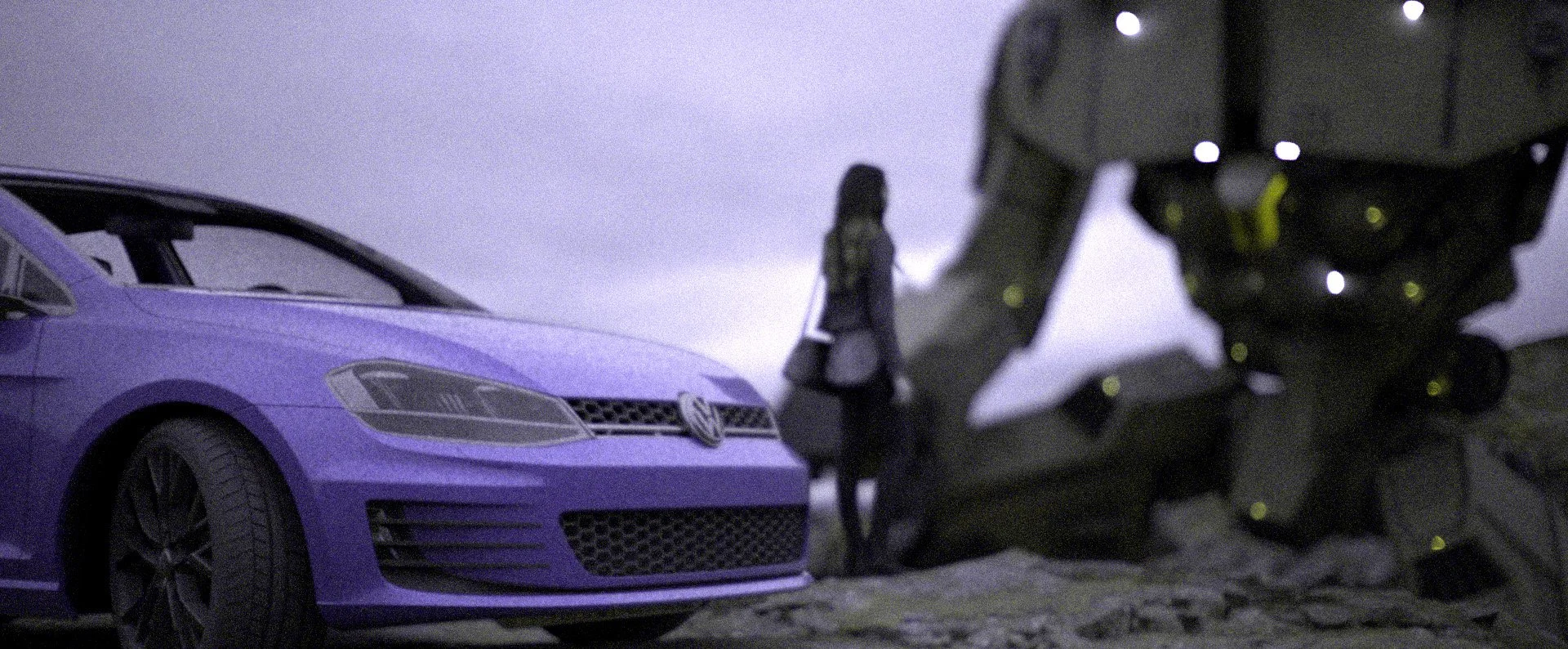
The images below shows the same scene but with a virtual matte box attached, the other image zooms in to demonstrate the difference caused by matte box.
Modular design for both 2D/3D
The framework could work for both flat field (2D) input and 3D scene, or a combination both such as a series of 2D images with z-depth information, which is normally the case for movie/TV post production during the composition stage. Since directly rendering camera effects using the 3D software produces irreversible results, i.e., it is impossible to change the camera parameters after the image is rendered, most productions prefer having the camera effect added during composition.
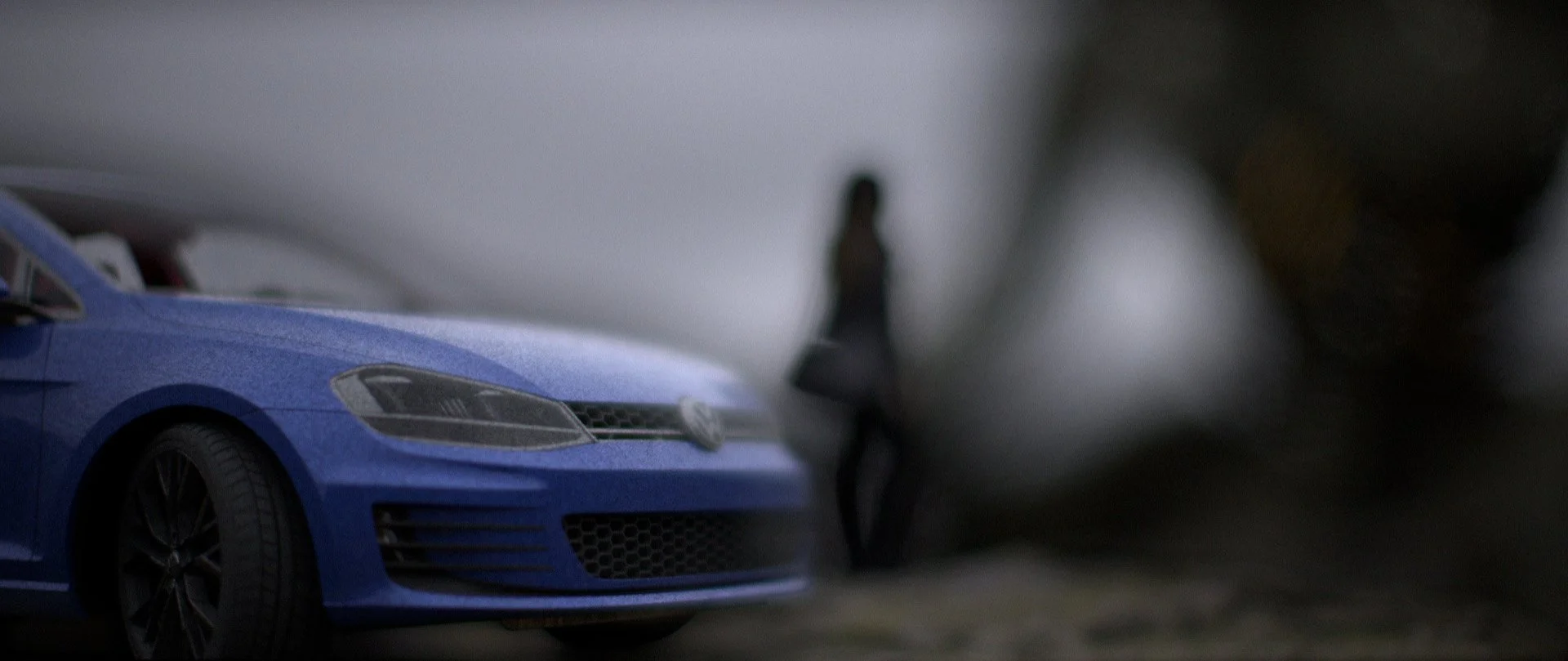
The image below shows a focus racking effect from foreground to the back ground, using a Canon EF 50mm f/1.2 L lens wide open.

When used in the second imaging pipeline, the framework also allows world unit change at no cost. Whereas the same operation would have broken the software for a large 3D scene with billions of poly, dozens of characters with rigging, and countless special effects. The image below shows the same scene but scaled down 10 times, as a result, the focus distance became significantly shorter and the depth of field ended up as thin as a sheet of paper.

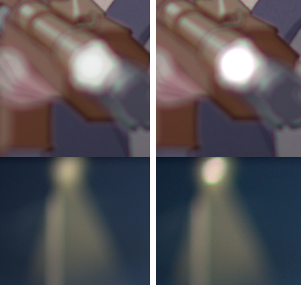
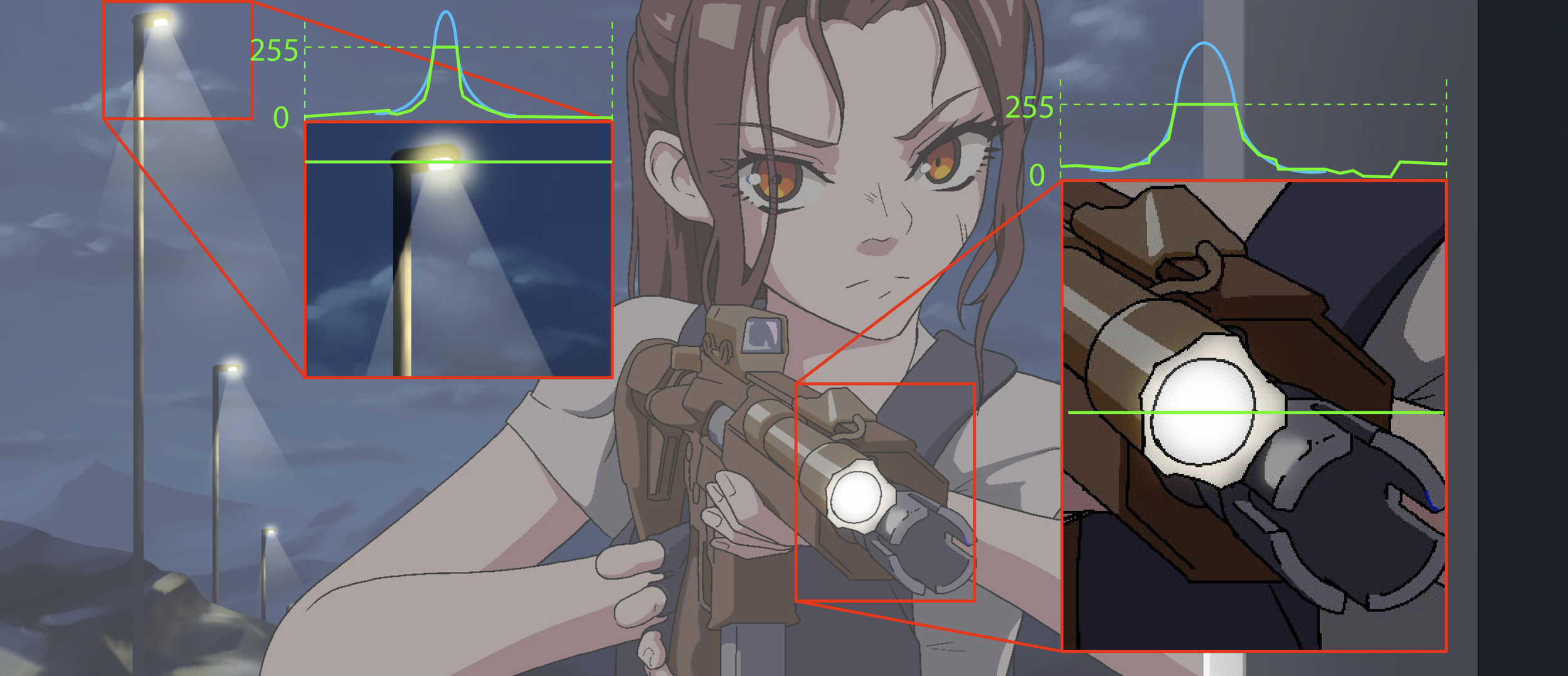
For 2D (hand drawn especially) animation, they are almost done exclusively in 8-bit. This would then create a highlight clipping problem, as their true value are capped at the 8-bit maximum, as shown in the image to the left.
Traditionally, some attempts of solving this problem involves setting up a threshold and a maximum value. But this tend to ignore the value variance within the scene and create highlights that are overly uniform. Not to mention the highlights created this way are also plateaued at the top, effectively making another clipping, just with higher values.
However, empirically, the size of the highlight within the image is often correlated with its value. Using this principle, we could reconstruct the highlight by fitting them with a Gaussian distribution, thus restoring both the value and the variance while also keeping the top organic.
Imager emulation
Imager not only allows the framework to produce RGB images, it also supports other features such as testing the effect of UVIR glass, CFA and MLA, even film effects such as halation and spectral responses.
The image on the right shows the ISO 12233 chart shot through a Zeiss Hologon 15mm f/8 lens, but the thickness of the UVIR glass in front of the imager increases gradually. This is one of the many reasons that vintage glass seems to perform less desirably on modern digital camera compare to when they are on a film camera.
The wavelength probability density function allows the framework to also emulate film spectral responses. And since it already runs on billions of rays samples, several millions of film grains can also be added without much performance cost. Each grain has its own development, density, and growth attribute, together they made it possible to simulate film negatives (please do note that this combined with density curve and film spectral response will make later inversion as complex as real film negatives…).
The framework could also simulate other phenomena associated with film. For example, when light passes through the film, if there is not a carbon backing, they may be reflected by the film plate and enter the film again, causing a colored halo. This process is often called halation and is replicable as well using the framework, as shown in the image below.
Creative effects
Physical effects by no means suppresses artistic freedom, rather, it releases more freedom than qualitive slider-based operations. For true creativity comes not from random and spontaneous accidents, but controlled and motivated decisions.
Emulsion order displacement
Film base are made from several layers of different emulsions, for typical color negative, the orders are yellow dye (blue color) - purple dye (green color) - cyan dye (red color), each with their spectral response and density curve.
Since the frameworks models both the spectral response and density curve, it is possible to swap the order of the emulsion layers and get an effect similar to some Lomography film. The image on the left shows a BRG order instead of BGR.

Haze on the lens surfaces
For vintage lenses, quite often their surfaces are no longer in pristine conditions, but rather, covered in scratches and dusts. These imperfections tend to scatter the rays and makes bright lights in the frame to spill over to the rest of the image.
The example on the right shows the scene rendered using a Contax Zeiss Sonnar 50mm f/1.5, but from top to bottom with increasingly more haze on the surfaces, which significantly reduces the global contrasts.
The haze effect can also functions as a white mist filter. The difference between haze and bloom (like the ones in Unity and Unreal) is that the haze effect is not clipped by a value threshold and is directional.
(technically, dusts and fungus also will show up in defocused bokeh as textures and patterns. For example, dusts around the pupil plane will create small local concentric circles. This phenomenon is caused by diffraction and interference, which is why many of those local patterns look like mini Airy disks. While the framework could perform diffraction star simulation, it is based on the lens aperture, it does not fully model the wavefront phase and amplitude change as it propagates across the lens, which makes accurate internal bokeh pattern hard to replicate. However, larger entrance pupil also reduces the effect dusts, scratches, or fungi has on the final image, so a generic scattering model actually models the haze effect very well)
Lens element transform
An easy and practical lens modification that people often perform on their inexpensive vintages lenses is reversing the front or rear element. Since optical aberrations (either correction or introduction) of each surface is not commutative, reversing a lens element could drastically change the characteristic of a lens.
The Helios-44 is possibly the most popular vintage lens out there, this once $5 soviet lens has jumped to around $150 after being used in the 2022 the Batman and 2024 Dune Part II. One common mod people do on the Helios is to reverse the front element. This will make the second surface to introduce an absurd amount of coma, astigmatism, and spherical aberration, which remains under-corrected throughout the lens. The image pair on the left shows the ordinary result of Helios-44 (top) and when the front element is reversed (bottom).
In addition, the framework can also perform local transform, which allows an element to be translated or rotated, thus replicating more artifacts.
Full production IO support
The framework is designed specifically for the media production workflow, so that only a minimum amount of modification is needed to the pipeline after introducing this imaging system simulation step.
When used in 3D post compositing, the framework supports reading EXR files with multiple channels, such as alpha and z-depth. The framework can also output render files as EXR to preserve the high bit depth info needed for further editing. if the input contains other AOVs, the framework also preserves them [1].
For 2D productions such as hand-drawn animation, the framework provides support to the normal 8-bit workflow but also allows extension to be made to compensate for the lack of malleable dynamic range.
[1] It should be noted that while AOVs are preserved, their meaning may not hold as well. Things like object ID, indirect, motion vectors, etc. are computer graphics concepts, not physical measurements. So when they are fed through a system based on physical principals, their meaning tend to be distorted. It is best to apply those AOVs before popping everything through an imaging system.
Diffraction
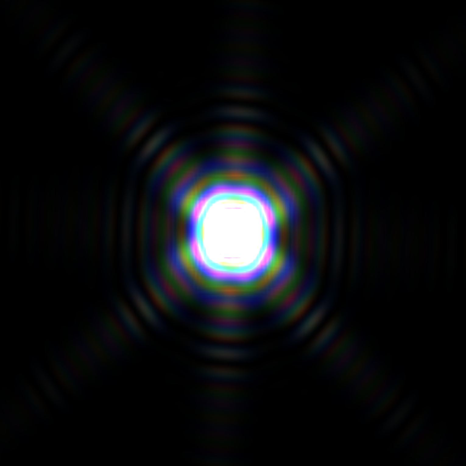
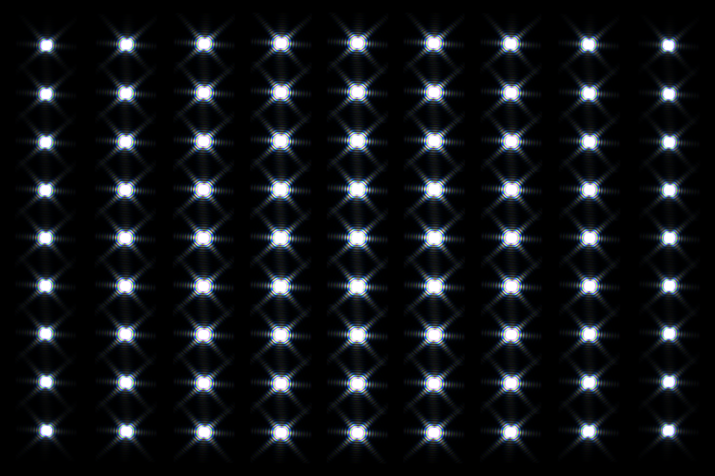
While the effect of diffraction is not visible in most scenarios of photographic applications, it will show up when the aperture is stopped down and there are bright point lights in the scene.
The framework is based on geometric spectral ray tracing and not angular spectrum method wave propagation, so diffraction is not the natural product of the process. But by using the image of the system aperture stop, field dependent diffraction can still be simulated.
Other features
Lens prescription data.
The framework automatically calculates the prescription data of the lens or the imaging system, reporting common data needed for design or inspecting the system.
Automatic material search.
The framework contains over three thousand optical materials, their formula and corresponding coefficients. This database allows the framework to calculate the RI of the material at any wavelength, and consequently the Abbe number at arbitrary Fraunhofer lines. After normalizing the data, this then enables the framework to find the matching material given only the RI and Abbe number.
Through focus distortion based on energy density.
The framework supports distortion calculation not by chief ray angle but by calculating the energy centroid of spots. This allows the framework to also calculate off-focus distortion.
Polarization
Despite being mostly a geometric spectral ray tracer, the framework does contains the polarization attribute of each ray. This allows the tracing to also replicate reflectance differences along sagittal and parallel direction, or the use of CPL filters.